Home
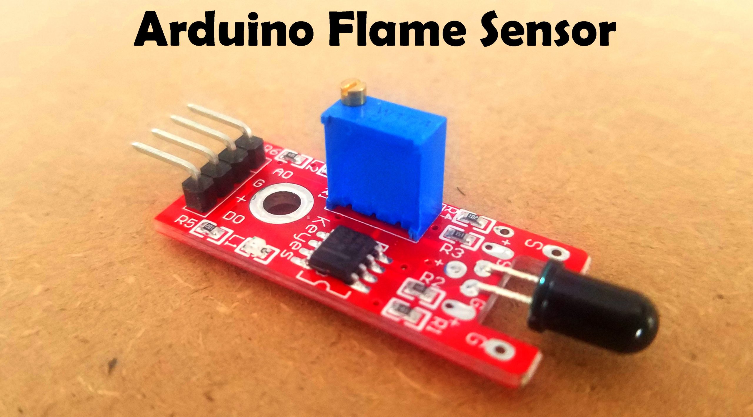
› Flame Sensor Wiring Diagram : FLAME SENSOR: 8 Steps : The ir flame sensor used in this project is shown below, these sensors are also called fire sensor module or flame detector sensor sometimes.
Flame Sensor Wiring Diagram : FLAME SENSOR: 8 Steps : The ir flame sensor used in this project is shown below, these sensors are also called fire sensor module or flame detector sensor sometimes.
Flame Sensor Wiring Diagram : FLAME SENSOR: 8 Steps : The ir flame sensor used in this project is shown below, these sensors are also called fire sensor module or flame detector sensor sometimes.. Arduino flame sensor diy | flame sensors, smoke detectors, and fire alarms are a part of our regular safety systems. The flame sensors available in the market with two categories one is having three pins (d0, gnd, vcc) and second one is having four pins (a0, d0, gnd by connecting sensor output pins with multimeter and showing towards flame with different angle and distance gives you describable details about. I would wire it in different ways and measure the changes in current/voltage when. In this post, we will interface the flame sensor with arduino. So handle them with great care.
Flame sensor is based on the principle that infrared ray is highly sensitive to flame. Flame sensor is an electronic device which is capable of sensing/detection of fire or a high temperature zone. This time i added the arduino uno. The charge on the three capacitors then drains through terminal e and the current detector amplifier 33 of the combustion. ② connect the development board to a pc via a serial wire and the.
DIY Flame Sensor Alarm Using KY-026 - Arduino Project Hub from hackster.imgix.net The flame sensor module also contains indicator leds. .wiring diagram wiring diagram (line) humidifier electronic air cleaner flame sensor probe 1 stage valve legend low voltage (24 vac) line voltage (120 vac) n. = normally open switch typical system wiring diagram 120. Male to female jumper wires. 15 319 просмотров 15 тыс. The wiring diagram below shows that the d0 pin of the. Simply, a pyroelectric flame sensor detects the typical spectral radiation of burning, organic substances such as wood, natural in practice, flame/fire detection is based on various detection techniques and sensor devices. It looks just like an led except it's black.
The flame sensors available in the market with two categories one is having three pins (d0, gnd, vcc) and second one is having four pins (a0, d0, gnd by connecting sensor output pins with multimeter and showing towards flame with different angle and distance gives you describable details about.
Route sensor wiring a sufficient distance from ignition and other high voltage or high current wiring to avoid electrical interference. You will see the complete wiring diagram for interfacing flame sensor with arduino and the. The flame sensors available in the market with two categories one is having three pins (d0, gnd, vcc) and second one is having four pins (a0, d0, gnd by connecting sensor output pins with multimeter and showing towards flame with different angle and distance gives you describable details about. Rev 4 wiring diagram parts list design worksheet duration. The ir flame sensor used in this project is shown below, these sensors are also called fire sensor module or flame detector sensor sometimes. The flame sensor module also contains indicator leds. Working of flame sensor with arduino. It gives an indication through an led i am using four pin flame sensor in this tutorial. Simply, a pyroelectric flame sensor detects the typical spectral radiation of burning, organic substances such as wood, natural in practice, flame/fire detection is based on various detection techniques and sensor devices. 15 319 просмотров 15 тыс. In this post, we will interface the flame sensor with arduino. Arduino uno is a open source microcontroller board based on atmega328p microcontroller. I recently found a 2 pin flame sensor.
The ir flame sensor used in this project is shown below, these sensors are also called fire sensor module or flame detector sensor sometimes. Everybody knows that reading flame sensor wiring diagram is beneficial, because we could get too much info online through the reading materials. Flame sensor is interfaced to arduino to detect flame. Flame sensor (model with an analog out). When we place a flame near flame sensor arduino automatically turns on the led and buzzer.
Flame Sensor Wiring Diagram from i.ytimg.com Male to female jumper wires. An acvoltageis applied to the flame sensor schematic circuit wiring diagram. The charge on the three capacitors then drains through terminal e and the current detector amplifier 33 of the combustion. It has 14 digital pins (out of which 6 pins can be used as pwm outputs), 6 analog inputs, on board. It is not a module and i couldn't find any wiring tutorials for these, just for basically you could wire this like any other photo diode or transistor. Further, if the lead wires are cut with a nipper or processed in other. It gives an indication through an led we are using four pin flame sensor in this tutorial. The ir flame sensor used in this project is shown below, these sensors are also called fire sensor module or flame detector sensor sometimes.
It has an infrared receiving tube specially designed to detect fire, and then convert the flame brightness into fluctuating level along with the kit you get access to detailed tutorials and wiring diagrams.
It looks just like an led except it's black. This video shows how to interface a flame sensor with arduino to detect fire and activate a buzzer, which shows the following: They're being installed in our homes, offices, and buildings in order to let us know of any fire accidents. You will see the complete wiring diagram for interfacing flame sensor with arduino and the. It's a vast topic and hence won't fit within the frame. In this post, we will interface the flame sensor with arduino. Simply we will design fire detector using arduino uno. 15 319 просмотров 15 тыс. Flame sensor should be kept at a reasonable distance from the source flame. ④ start the serial debugging software, and you can find the serial output changes along with the distance from the sensor to the fire. Arduino uno is a open source microcontroller board based on atmega328p microcontroller. Once the board sends a call to the gas valve to open, it monitors the current it generates a potential (voltage) at the flame sensing terminal; Slide the green wire with the red connector onto the terminal you removed the red wire from.
② connect the development board to a pc via a serial wire and the. This sensor is designed for use in reliably detecting open flames using an arduino or raspberry pi. Flame sensor (model with an analog out). Most of the time, you would hire someone to install the safety devices in your homes. It has an infrared receiving tube specially designed to detect fire, and then convert the flame brightness into fluctuating level along with the kit you get access to detailed tutorials and wiring diagrams.
Flame Sensor Arduino, Fire Sensor Arduino, Circuit and ... from www.electroniclinic.com Rev 4 wiring diagram parts list design worksheet duration. Flame sensor uv tron® r2868 schematic circuit wiring diagram. It has an infrared receiving tube specially designed to detect fire, and then convert the flame brightness into fluctuating level along with the kit you get access to detailed tutorials and wiring diagrams. I would wire it in different ways and measure the changes in current/voltage when. Flame sensor interfacing to arduino. The below image is the arduino fire sensor circuit diagram, it shows how to interface the fire sensor module with arduino. .wiring diagram wiring diagram (line) humidifier electronic air cleaner flame sensor probe 1 stage valve legend low voltage (24 vac) line voltage (120 vac) n. It looks just like an led except it's black.
Flame sensing rods stick out into the flame and connect back to the furnace board.
Everybody knows that reading flame sensor wiring diagram is beneficial, because we could get too much info online through the reading materials. 15 319 просмотров 15 тыс. I would wire it in different ways and measure the changes in current/voltage when. This sensor is designed for use in reliably detecting open flames using an arduino or raspberry pi. The ir flame sensor used in this project is shown below, these sensors are also called fire sensor module or flame detector sensor sometimes. ④ start the serial debugging software, and you can find the serial output changes along with the distance from the sensor to the fire. Refer to figure 5.5 for sequence diagrams. Arduino uno is a open source microcontroller board based on atmega328p microcontroller. = normally closed switch n. It has an infrared receiving tube specially designed to detect fire, and then convert the flame brightness into fluctuating level along with the kit you get access to detailed tutorials and wiring diagrams. Once the board sends a call to the gas valve to open, it monitors the current it generates a potential (voltage) at the flame sensing terminal; Flame sensor arduino circuit diagram: It has 14 digital pins (out of which 6 pins can be used as pwm outputs), 6 analog inputs, on board.