Home
› Trailer Electrical Diagram - Trailer Wiring Diagrams Johnson Trailer Co - 2000 coachmen catalina wiring diagram sportscoach battery solenoid or switch where to start rv electricity 12 volt dc 120 diagrams 1998 coachman caravan jeep tv feed forest river 1973 thermostat 7 pin trailer connector 73 dodge class a chassis fuse box santara 220rk etrailer travel electrical gmcmi me 4984 slide out will not retract for atwood.
Trailer Electrical Diagram - Trailer Wiring Diagrams Johnson Trailer Co - 2000 coachmen catalina wiring diagram sportscoach battery solenoid or switch where to start rv electricity 12 volt dc 120 diagrams 1998 coachman caravan jeep tv feed forest river 1973 thermostat 7 pin trailer connector 73 dodge class a chassis fuse box santara 220rk etrailer travel electrical gmcmi me 4984 slide out will not retract for atwood.
Trailer Electrical Diagram - Trailer Wiring Diagrams Johnson Trailer Co - 2000 coachmen catalina wiring diagram sportscoach battery solenoid or switch where to start rv electricity 12 volt dc 120 diagrams 1998 coachman caravan jeep tv feed forest river 1973 thermostat 7 pin trailer connector 73 dodge class a chassis fuse box santara 220rk etrailer travel electrical gmcmi me 4984 slide out will not retract for atwood.. This car is designed not just to travel one location to another but also to carry heavy loads. Trailer wiring connectors various connectors are available from four to seven pins that allow for the transfer of power for the lighting as well as auxiliary functions such as an electric trailer brake controller, backup lights, or a 12v power supply for a winch or interior trailer lights. Collection of travel trailer wiring schematic. Check out the tinyrevolution.us website for full instructions. 7 wire trailer circuit, 6 wire trailer circuit, 4 wire trailer circuit and other trailer wiring diagrams.
A wiring diagram is a simplified traditional pictorial representation of an electrical circuit. Trailer wiring connectors various connectors are available from four to seven pins that allow for the transfer of power for the lighting as well as auxiliary functions such as an electric trailer brake controller, backup lights, or a 12v power supply for a winch or interior trailer lights. Above we have describes the main types of trailer wiring diagrams. Check out the tinyrevolution.us website for full instructions. Assortment of jayco trailer wiring diagram.
Wiring Diagrams from site.drawtite.com Trailer wiring diagrams 4 way systems. A wiring diagram is a simplified traditional pictorial representation of an electrical circuit. Trailers with electric brakes need them too. Check out the tinyrevolution.us website for full instructions. Connections and basic information · da's place: Here's a diagram that i used for reference. Below is the generic schematic of how the wiring goes. Trailer wiring diagrams trailer wiring connectors various connectors are available from four to seven pins that allow for the transfer of power for the lighting as well as auxiliary functions such as an electric trailer brake controller, backup lights, or a 12v power supply for a winch or interior trailer lights.
This r pod trailer wiring diagram model is far more appropriate for sophisticated trailers and rvs.
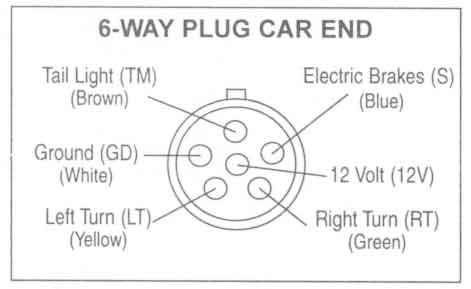
2000 coachmen catalina wiring diagram sportscoach battery solenoid or switch where to start rv electricity 12 volt dc 120 diagrams 1998 coachman caravan jeep tv feed forest river 1973 thermostat 7 pin trailer connector 73 dodge class a chassis fuse box santara 220rk etrailer travel electrical gmcmi me 4984 slide out will not retract for atwood. These power cords come in two amperages: 4 pin trailer wiring diagram. Collection of electric trailer brake wiring schematic. This car is designed not just to travel one location to another but also to carry heavy loads. It reveals the components of the circuit as streamlined shapes, as well as the power and also signal connections between the devices. Enclosed trailers of all types are connected to external power sources in the same way. 12n (normal) electrics wiring diagram for the exterior lighting on a trailer or caravan from western towing A wiring diagram is a streamlined traditional photographic depiction of an electric circuit. Electric trailer jack wiring diagram download. Contents show understanding ac vs dc power. By law, trailer lighting must be connected into the tow vehicle's wiring system to provide trailer running lights, turn signals and brake lights. Rvs are powered by two electrical systems, ac and dc.
By law, trailer lighting must be connected into the tow vehicle's wiring system to provide trailer running lights, turn signals and brake lights. Otherwise, the arrangement will not function as it should be. White pin for the floor. We recommend these standards because they are pretty universal. Pump are all run off separate circuits as shown on electrical diagram.
Trailer Wiring Diagram And Installation Help Towing 101 from www.curtmfg.com Okay, so this is dumb, but i video taped the guy explaining what to do with my new travel trailer. Pump are all run off separate circuits as shown on electrical diagram. Above we have describes the main types of trailer wiring diagrams. Click on the image to enlarge, and then save it to your computer by right clicking on the image. This is where i got the diagram. Use the rv electrical diagram we made below to get an understanding of what powers what and to learn how an rv electrical system works. A wiring diagram is a streamlined traditional photographic depiction of an electric circuit. We recommend these standards because they are pretty universal.
Enclosed trailers are often used for camping, portable shops, riding toy operating ac appliances or tools.
That said, for specific situations, there are industrial standards with different connectors and wire arrangements. Connections and basic information · da's place: Collection of electric trailer brake wiring schematic. Otherwise, the arrangement will not function as it should be. Trailers with electric brakes need them too. 11/10 for 2011 wiring diagrams note: This r pod trailer wiring diagram model is far more appropriate for sophisticated trailers and rvs. This is where i got the diagram. White pin for the floor. To connect the electric system of your trailer to the vehicle, you will be using special connector. 12n (normal) electrics wiring diagram for the exterior lighting on a trailer or caravan from western towing Now, most electrical experts will agree that the converter that comes from the factory in most rvs, while functional, is not the best method for charging your house batteries. Use the rv electrical diagram we made below to get an understanding of what powers what and to learn how an rv electrical system works.
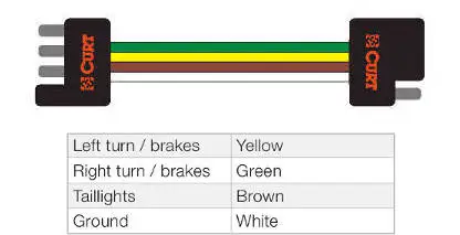
Custom fit vehicle trailer wiring harness are available for all makes of vehicles including ford, dodge, chevy, honda and toyota. Right turn signal / stop light (green), left turn signal / stop light (yellow), taillight / license / side marker (brown) and a ground (white). In fact, that is probably an understatement. A wiring diagram is a streamlined traditional photographic depiction of an electric circuit. Below is the generic schematic of how the wiring goes.
Trailer Wiring Diagrams Johnson Trailer Co from johnsontrailerco.com 4 way flat molded connectors allow basic hookup for three lighting functions; If your vehicle is not equipped with a working trailer wiring harness, there are a number of different solutions to provide the perfect fit for. Above we have describes the main types of trailer wiring diagrams. Rvs are powered by two electrical systems, ac and dc. Almost all rvs come with a power cord to plug into the electrical pedestal at a campground (developed campgrounds with available hookups, anyway). Check out the tinyrevolution.us website for full instructions. 4 pin trailer wiring diagram. Trailer wiring connectors various connectors are available from four to seven pins that allow for the transfer of power for the lighting as well as auxiliary functions such as an electric trailer brake controller, backup lights, or a 12v power supply for a winch or interior trailer lights.
Creating a volt electrical hookup to any trailer is a straightforward project.
This is also known as a shore power connection. Trailers with electric brakes need them too. 12n (normal) electrics wiring diagram for the exterior lighting on a trailer or caravan from western towing Here's a diagram that i used for reference. Collection of travel trailer wiring schematic. In fact, that is probably an understatement. Collection of electric trailer brake wiring schematic. A wiring diagram is a streamlined traditional photographic depiction of an electric circuit. This car is designed not just to travel one location to another but also to carry heavy loads. Now, most electrical experts will agree that the converter that comes from the factory in most rvs, while functional, is not the best method for charging your house batteries. 4 pin trailer wiring diagram. Pump are all run off separate circuits as shown on electrical diagram. These instructions are really great.