Home
› Or Circuit Diagram - Wiring Diagram Marvelous Lights In Series Or Parallel For ... / We use circuit symbols to draw diagrams of electrical circuits, with straight lines to show the wires.
Or Circuit Diagram - Wiring Diagram Marvelous Lights In Series Or Parallel For ... / We use circuit symbols to draw diagrams of electrical circuits, with straight lines to show the wires.
Or Circuit Diagram - Wiring Diagram Marvelous Lights In Series Or Parallel For ... / We use circuit symbols to draw diagrams of electrical circuits, with straight lines to show the wires.. Or diagram is a drawing or plan of the digital logic or function, it is not able to actually do anything only tell a person something about this logic function. Or gate ak aisa circuit he jismen two input our one output hota hen. Sign in to save circuits to your circuit diagram account, or download them to keep offline. An elementary is a schematic or one line diagram showing the basic operation of a circuit and is best used for troubleshooting or discussing. Circuit diagrams, aka schematics, are line drawings that show how a circuit's components are connected together.
Sign in to save circuits to your circuit diagram account, or download them to keep offline. A circuit diagram is a visual representation of a complete circuit of an electronic or electrical equipment. It offers you all the logic components, like xor, nand, or, xnor, not, and. Circuit diagram.org also provides a full educational system to students new to electronics. The diagram shows some common circuit symbols.
NOR gate S-R latch : DIGITAL INTEGRATED CIRCUITS from www.learningelectronics.net 24v to 220v 1000w dc ac sine wave inverter for photovoltaic solar system. Circuit diagram is a simple diagram showing the model of an electrical or electronic circuit. 12v to 24v dc converter power supply circuit diagram. An elementary is a schematic or one line diagram showing the basic operation of a circuit and is best used for troubleshooting or discussing. A circuit diagram (electrical diagram, elementary diagram, electronic schematic) is a graphical representation of an electrical circuit. The illustration is populated with several globally recognized symbols and icons representing the components that are connected with the help of the lines in order to work collectively. Pwm or pulse width modulation is a very common method used for controlling the power across devices like motor, light etc. A circuit diagram, or a schematic diagram, is a technical drawing of how to connect electronic components to get a certain function.
A circuit diagram also known as an electrical diagram, wiring diagram, elementary diagram, or electronic schematic is a simplified conventional pictorial representation of an electrical circuit.
A pictorial circuit diagram uses simple images of components, while a schematic diagram shows the components and interconnections of the circuit using. Learn what an or gate is, its definition, working principle, transistor circuit diagram & symbol, and how an or gate works. The diagram shows some common circuit symbols. Or gate ak aisa circuit he jismen two input our one output hota hen. Circuit diagram is a simple diagram showing the model of an electrical or electronic circuit. Yadi ap kisi bhi ak input men input doge to apkl output men one ya high prapt hoga yadi ap dono men input 1. 24v to 220v 1000w dc ac sine wave inverter for photovoltaic solar system. Exclusive or gate (exor gate) or xor gate the output of an exclusive or gate is high if its one input, but not both is high. A circuit diagram, or a schematic diagram, is a technical drawing of how to connect electronic components to get a certain function. These two different types of circuit diagrams are called pictorial (using basic images) or schematic style (using. Create schematic or pictorial circuit diagrams for any audience. It shows the components of the circuit as simplified standard symbols, and the power and signal connections. Or gate circuit diagram truth table ic symbol formula how to make in hindi test video conditions etc all data avaliable uses.
They serve as a map or plan for schematic diagrams are made up of two things: Yadi ap kisi bhi ak input men input doge to apkl output men one ya high prapt hoga yadi ap dono men input 1. Or diagram is a drawing or plan of the digital logic or function, it is not able to actually do anything only tell a person something about this logic function. Interfacing high power load can be done in many ways, such as using voltage divider resistors, transformer, or optocoupler. An elementary is a schematic or one line diagram showing the basic operation of a circuit and is best used for troubleshooting or discussing.
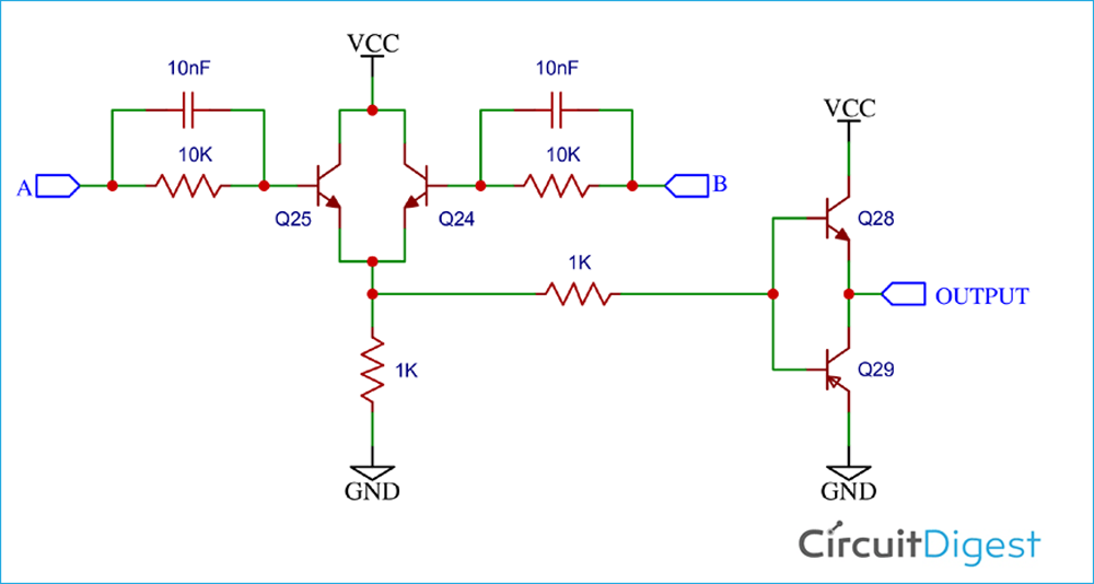
Designing OR Gate Circuit using Transistor from circuitdigest.com 24v to 220v 1000w dc ac sine wave inverter for photovoltaic solar system. Circuit diagrams, aka schematics, are line drawings that show how a circuit's components are connected together. A circuit diagram, or a schematic diagram, is a technical drawing of how to connect electronic components to get a certain function. It shows the components of the circuit as simplified standard symbols, and the power and signal connections. A circuit diagram also known as an electrical diagram, wiring diagram, elementary diagram, or electronic schematic is a simplified conventional pictorial representation of an electrical circuit. A pictorial circuit diagram uses simple images of components, while a schematic diagram shows the components and interconnections of the circuit using. Create schematic or pictorial circuit diagrams for any audience. Symbols that represent the components in the circuit, and lines that represent the connections.
Yadi ap kisi bhi ak input men input doge to apkl output men one ya high prapt hoga yadi ap dono men input 1.
Design circuits online in your browser or using the desktop application. Yadi ap kisi bhi ak input men input doge to apkl output men one ya high prapt hoga yadi ap dono men input 1. Exclusive or gate (exor gate) or xor gate the output of an exclusive or gate is high if its one input, but not both is high. A pictorial circuit diagram uses simple images of components, while a the presentation of the interconnections between circuit components in the schematic diagram does not necessarily correspond to the physical arrangements. Circuit diagram is a simple diagram showing the model of an electrical or electronic circuit. Circuit diagram.org also provides a full educational system to students new to electronics. It represents all the aspects of the system under pictorial schematic diagrams, or pictorial circuit diagrams are essentially the same thing with the same purpose, but they use pictures of components. It offers you all the logic components, like xor, nand, or, xnor, not, and. Symbols that represent the components in the circuit, and lines that represent the connections. An elementary is a schematic or one line diagram showing the basic operation of a circuit and is best used for troubleshooting or discussing. A circuit diagram is a visual display of an electrical circuit using either basic images of parts or industry standard symbols. 24v to 220v 1000w dc ac sine wave inverter for photovoltaic solar system. (working principle & circuit diagram).
Learn what an or gate is, its definition, working principle, transistor circuit diagram & symbol, and how an or gate works. Symbol usage depends on the audience viewing the diagram. Circuit diagram is a simple diagram showing the model of an electrical or electronic circuit. The truth table of or gate is show in figure. Design circuits online in your browser or using the desktop application.
What are the Low Voltage Fuses? - Rewirable Fuse & Totally ... from circuitglobe.com Pwm or pulse width modulation is a very common method used for controlling the power across devices like motor, light etc. A wiring diagram is a comprehensive diagram of each electrical circuit system showing all the connectors, wiring, terminal boards, signal connections (buses) between the devices and electrical or electronic components of the circuit. 12v to 24v dc converter power supply circuit diagram. An elementary is a schematic or one line diagram showing the basic operation of a circuit and is best used for troubleshooting or discussing. A circuit diagram is a graphical representation of an electrical circuit. Exclusive or gate (exor gate) or xor gate the output of an exclusive or gate is high if its one input, but not both is high. A circuit diagram also known as an electrical diagram, wiring diagram, elementary diagram, or electronic schematic is a simplified conventional pictorial representation of an electrical circuit. (working principle & circuit diagram).
Hello readers, we frequently add new circuit diagrams, so do not forget to come.
Interfacing high power load can be done in many ways, such as using voltage divider resistors, transformer, or optocoupler. This free circuit diagram software allows you to debug circuit behavior with oscilloscope, navigate running circuits hierarchy, and create unrestricted circuit hierarchy with multi bit buses on its intuitive graphical user interface. A wiring diagram is a comprehensive diagram of each electrical circuit system showing all the connectors, wiring, terminal boards, signal connections (buses) between the devices and electrical or electronic components of the circuit. It offers you all the logic components, like xor, nand, or, xnor, not, and. A circuit diagram is a visual representation of a complete circuit of an electronic or electrical equipment. Electric circuits can be series or parallel. The technician creates a circuit diagram as a guideline for implementing circuit design or for communication. It represents all the aspects of the system under pictorial schematic diagrams, or pictorial circuit diagrams are essentially the same thing with the same purpose, but they use pictures of components. A circuit diagram (also known as an electrical diagram, elementary diagram, or electronic schematic) is a simplified conventional graphical representation of an electrical circuit. Circuit diagrams are used for illustrating different kinds of electrical circuits. A circuit diagram (electrical diagram, elementary diagram, electronic schematic) is a graphical representation of an electrical circuit. Pwm or pulse width modulation is a very common method used for controlling the power across devices like motor, light etc. Symbols that represent the components in the circuit, and lines that represent the connections.